-
TOTAL₹0.00
-
Call us Now
-
Send mail
-
Send mail
-
Call us Now
The role of Dynamic Braking Resistors in VFD
Braking resistors in Variable Frequency Drive(VFD) increase the braking torque capability, producing faster and more controlled braking. The Braking resistor dissipates regenerated power to keep the bus voltage from exceeding the rated limit of the drive.
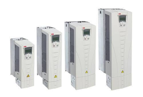
Variable Frequency Drives (VFD) have brought about a quiet revolution in the universe of electro-mechanical systems. Their ability to control the speed and torque of AC motors results in major energy savings and increasing the life span of the motors. Since AC motors are one of the largest energy consuming devices in industrial applications all over the world, the impact of VFDs is enormous.
AC induction motors are mostly fixed frequency devices by design, operating at 50Hz or 60Hz depending on the supply frequency of the grid in each country. However, when appended with a Variable Frequency Drive, the motor input frequency and voltage can be adjusted. Before the advent of VFDs, mechanical methods like using belts, sheaves, or gearboxes were employed to reduce speed while the motor still ran at full speed. However, a VFD reduces the actual motor speed, which reduces the amps drawn by the motor. This directly results in reduction of energy drawn.
VFD is a power conversion device which converts fixed frequency, fixed voltage input power to a variable frequency, variable voltage power input to an AC induction motor. By slowing down the ramping up/down process of the motor speed, they also ensure reduction in mechanical wear and tear of the motor.
Some of the most popular applications of VFD based devices are:
- Industrial Automation systems
- Electric trains
- Electric and hybrid automobiles
- Elevators and Escalators
- Cranes and Hoists
VFDs consist of the following major components:
- Rectifiers– convert the fixed frequency, fixed voltage main supply to fixed DC voltage in the first step.
- DC Bus– smoothens out the ripples in the DC signal that is received from the rectifier.
- Inverter – converts the DC signal into an AC signal using pulse width modulation to control the signal frequency. This AC signal is fed as the input to the AC induction motor.
- Control Circuit– placed between the Inverter and the AC motor to receive and collate data from the various devices. Purpose is to control the various drive settings, output frequency and voltage of the Inverter. Plays a critical role in preventing excess current surges during the starting of the AC motor.
- Dynamic Braking Resistors (DBR)– When the AC motor has to be brought to a stop, the VFD with the aid of the braking resistor acts like an electrical braking system instead of employing mechanical braking. The excess energy present in the rotating system has to be dumped somewhere quickly and that is the basic function of the Dynamic Braking Resistor.
The critical role of Dynamic Braking Resistors
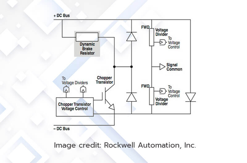
During the braking process of the motor, the operational mode changes from motoring (power flow from VFD to motor) to re-generating (from motor to VFD). While in the regenerative mode, the energy fed back tends to increase the DC bus voltage of the VFD. When the voltage exceeds the maximum DC bus capacity, the controller of the VFD turns on the Braking Resistor Unit for some time. This is when the excess energy is dissipated through the braking resistor in form of heat energy.
As a result of the braking, a very high amount of heat is produced in the motor. The rate at which the motor can be stopped is directly dependent on the rate at which the kinetic energy of the motor can be converted to heat and dissipated safely by the DBR. For small speeds of the motor, the DBR can absorb the heat themselves safely. For higher speeds, the DBR is fitted with an external heat shield which can absorb far greater amounts of heat.
The ohmic value of the DBR and the heat absorption threshold have to be accurately designed for each specific application. The drive manufacturer normally determines the power rating (watts) needed to prevent overheating during braking duty. In order to determine the resistor size, the inputs required are peak power, ohmic value and the duty cycle.
Dynamic braking is often the simplest and most cost effective means to dissipate the regenerative energy from AC motors, thus allowing the variable frequency drives to safely brake the load.
Simplified schematic of a Dynamic Braking Circuit
Dynamic Braking Resistors from KWK
KWK Resistors has been the preferred partner of several leading manufacturers of Elevators, Cranes, Locomotives and Material Handling systems for supplying Dynamic Braking Resistors.
KWK has the expertise to design and manufacture customised application specific resistors that are particularly good at handling high pulsed powers. Dynamic Braking Resistors from KWK come with varied resistance, power and current ratings. KWK Resistors also require very little service and maintenance. These heavy-duty resistors are designed to be rugged so as to withstand heavy loads and frequent start-stop cycles. Resistors come in different form factors like edge-wound and wire-wound resistors.
The KABR series from KWK are a range of Metal encased, Dynamic Braking Resistors. These resistors are economical and compact, offering excellent load life stability. Power dissipation of up to 1000W is available in this series. Assemblies of these resistors to achieve higher powers can be done with ease.
The KAHB series are high power Dynamic Braking Resistors with Aluminium casing. Power dissipation of up to 5000W is available in the KAHB series. Custom wattage can be designed and supplied on request.
The KCBR series of wire-wound braking resistors guarantee high stability and are designed to suit inverter drives of various makes. A wide range of resistance values are available in 0.5kW to 12kW Braking Resistors. The specially designed Helical Coil type resistor elements are used for high efficiency and faster cooling.
KWK’s product offering is not limited to these catalogue products. Numerous quantities of kW braking resistors are being custom designed for customers every day.
Braking Resistor Calculator
Check out the braking resistor calculator tool on our website for determining the Continuous Power (Pcont) from a known Braking power:
Try Our Braking Resistors Calculator

Author: Avinash Koorgailu
Director Operations responsible for manufacturing operations, engineering, and finance at KWK Resistors. The prime mover behind the creation of KWK resistors having worked in the USA, UK, and the Middle East before returning to India and joining hands at the KSI group.
Author: Anuradha C
An integral part of the content creation team at KWK Resistors, Anuradha is a corporate trainer in the IT/telecom domain with over 18 years of experience. She served in senior technical and management positions in Huawei and TCS for 10+ years
How useful was this?
Click on a star below to rate us out of 5 stars

 (8 votes, average: 4.75 out of 5)
One Reply to “The role of Dynamic Braking Resistors in VFD”
Tsar
August 19, 2020 at 9:11 pm
Need to know more about selection of braking resistance, its application and principle of function