-
TOTAL₹0.00
-
Call us Now
-
Send mail
-
Send mail
-
Call us Now
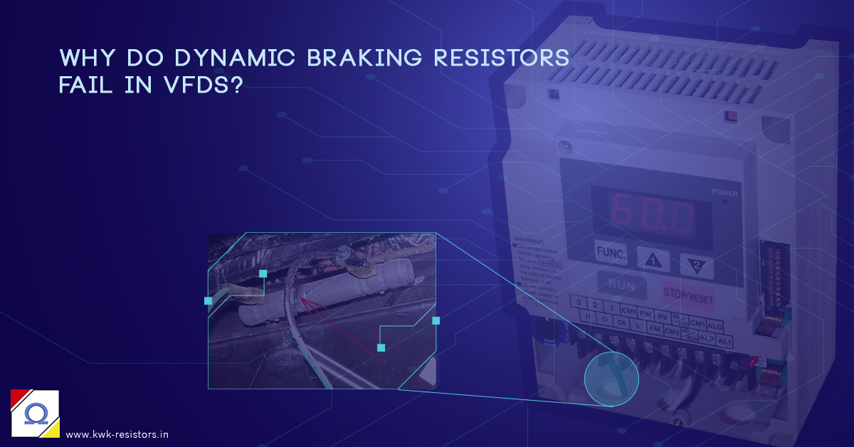
Why do Dynamic Braking Resistors fail in VFDs?
When a motor drive installed in an industrial automation device such as a crane, elevator or conveyor belt breaks down, the entire site activity comes to a halt. The equipment maintenance team is under great pressure to restore the functioning as soon as possible, to prevent loss of precious man-hours of work for everybody on-site.
Variable Frequency Drives attached to AC motors are prone to failure due to the following key reasons:
- Incorrect grounding termination
- Improper cable routing leading to EMI
- Overload or Instantaneous Overcurrent
- DC Bus Overvoltage
DC Bus Overvoltage
Out of all the reasons listed above, DC Bus Overvoltage is the most common issue. Trouble-shooting this issue primarily leads to examining the condition of the Dynamic Braking Resistor circuit.
Related: The role of Dynamic Braking Resistors in VFD
The critical role played by DBR in VFD devices has been explored in detail in our earlier blog. Click here to know more about this.
It is often noticed that the top reasons for failure of any industrial equipment involves improper handling of Dirt, Heat, and Moisture. This holds true even in DBRs. Inefficient handling of excess heat generated is the key cause of failure in DBRs. There are three main causes for this failure:
Improper threshold setting for DBR
The VFD needs to set the voltage threshold at which DBR should be enabled. This value should be set after careful analysis of the RMS input voltage. For example, on a 220V line, if the average voltage fluctuates by about 2% (up to 228V), then the threshold for DBR should be set at 230V to make sure that DBRs are not triggered during normal operation. In other words, the trigger voltage for the DBR should set above the fluctuations in the line voltage. The line voltage fluctuation should be managed independently, and the DBR should not be burdened with this scenario. This is to minimise the wear and tear of the DBR.
DBR Sizing
This seems like a minor design aspect but it is actually a very critical point to consider. Resistor sizing critically depends on duty cycle which is a measure of the percentage of time braking is enabled in relation to the total cycle time.
Duty cycle = braking time / total cycle time
Braking time should be limited to under 10% of total cycle time. This gives the braking resistor enough time to dissipate the heat that is generated during braking. If the braking cycle increases higher than this threshold, then the VFD is at risk of burning the DBR. This could lead to damage of the Braking Unit and the VFD.
DBR burnout occurs from wrong sizing. If the sizing computations are not done correctly, vendors may use a smaller resistor than what is required and this could lead to burnout.
To derive the size of the resistor we need to know three things: the energy per stop, the duty cycle and the ohmic value. The first two are usually combined into one variable that is, the power of the resistor.
DBR construction quality
DBRs come in different sizes and form factors, from simple heating elements in metal cages to potted brick shaped to wire wound cylindrical resistors. The selection of a specific type should be made after a careful computation of the expected peak current and voltage that would be generated in the VFD during braking. Care should be taken to select the DBR that can handle the expected peak power for at least one second.
Poor quality of resistor construction, using inferior materials are another very common cause of failure. Such resistors may be priced very low and come in attractive packaging. But they cannot handle peak loads and cause major downtime and large scale equipment damage. It’s important to invest in high quality materials for the various parts such as wire winding, metal film, encasing, coil type.
Additional precautions
Connection between the external DBUs and VFD is sensitive to polarity. So if the connections are reversed, it would end up damaging the drive or the DBR or both!
It is also very important to add overload protection to the circuit. This protection is connected in series with the contactor that disconnects power from the drive when the over load current limit is exceeded. Overload protection is a small price to pay when compared with the equipment damage that could result in an unprotected drive.
Modern VFDs have separate LED and alarm beep indications during both Dynamic braking and Overload conditions.
DBR failure is not an on-site issue that cannot be predicted or prevented. We need a change in mind-set. It’s actually a design issue that can be taken care of during the component design phase itself. With careful planning and abundant precaution, equipment damage or down time can be effectively minimised.
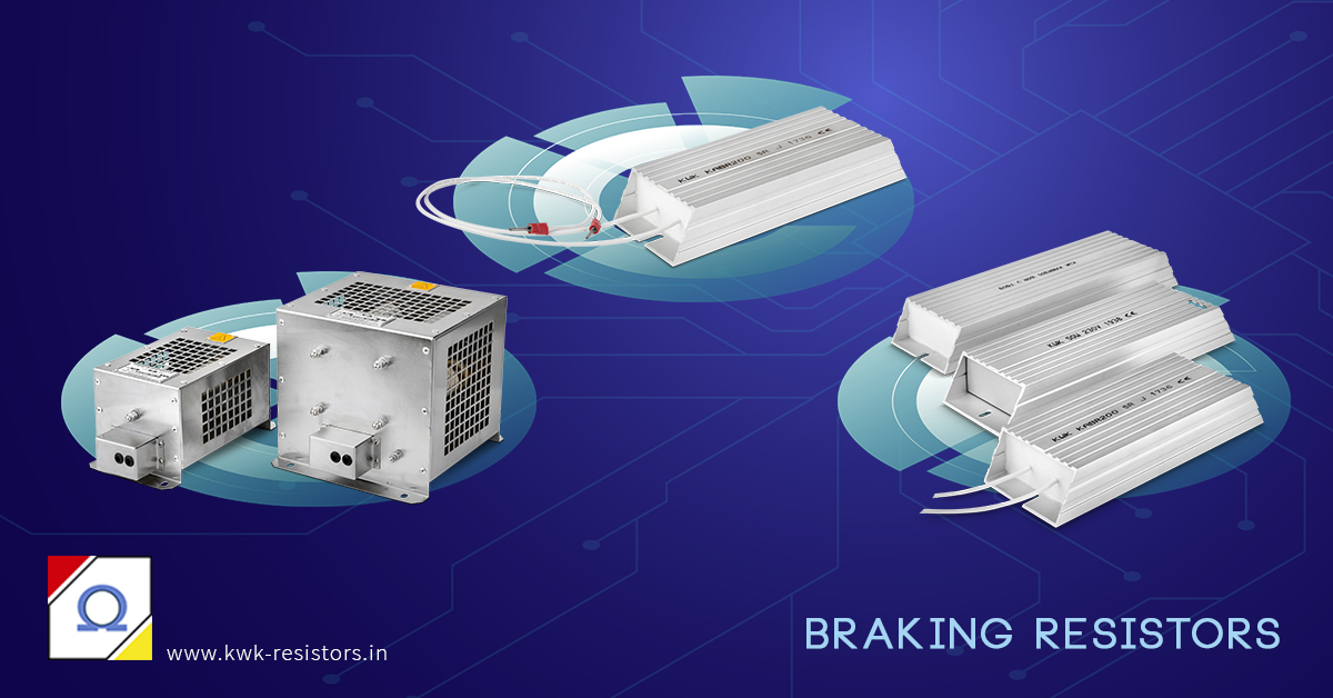
Dynamic Braking Resistors from KWK
KWK Resistors has been the preferred partner of several leading manufacturers of Elevators, Cranes, Locomotives and Material Handling systems for supplying Dynamic Braking Resistors. Our product quality and wide range of resistor offerings is the primary reason behind their trust imposed in us.
KWK has the expertise to design and manufacture customised application specific resistors that are particularly good at handling high pulsed powers. Dynamic Braking Resistors from KWK come with varied resistance, power and current ratings. KWK Resistors also require very little service and maintenance.
These heavy-duty resistors are designed to be rugged so as to withstand heavy loads and frequent start-stop cycles. Resistors come in different form factors like edge-wound and wire-wound resistors.
The KABR series from KWK are a range of Metal encased, Dynamic Braking Resistors. These resistors are economical and compact, offering excellent load life stability. Power dissipation of up to 1000W is available in this series. Assemblies of these resistors to achieve higher powers can be done with ease.
The KAHB series are high power Dynamic Braking Resistors with Aluminium casing. Power dissipation of up to 5000W is available in the KAHB series. Custom wattage can be designed and supplied on request.
The KCBR series of wire-wound braking resistors guarantee high stability and are designed to suit inverter drives of various makes. A wide range of resistance values are available in 0.5kW to 12kW Braking Resistors. The specially designed Helical Coil type resistor elements are used for high efficiency and faster cooling.
KWK’s product offering is not limited to these catalogue products. Numerous quantities of kW braking resistors are being custom designed for customers every day.
Braking Resistor Calculator
Check out the braking resistor calculator tool on our website for determining the Continuous Power (Pcont) from a known Braking power.
Try Our Braking Resistors Calculator

Author: Avinash Koorgailu
Director Operations responsible for manufacturing operations, engineering, and finance at KWK Resistors. The prime mover behind the creation of KWK resistors having worked in the USA, UK, and the Middle East before returning to India and joining hands at the KSI group.
Author: Anuradha C
An integral part of the content creation team at KWK Resistors, Anuradha is a corporate trainer in the IT/telecom domain with over 18 years of experience. She served in senior technical and management positions in Huawei and TCS for 10+ years
How useful was this?
Click on a star below to rate us out of 5 stars

 (4 votes, average: 4.75 out of 5)
One Reply to “Why do Dynamic Braking Resistors fail in VFDs?”
vilas shivaji bhaskar
August 6, 2021 at 12:21 pm
Please send Technical data Sheet required for DBR